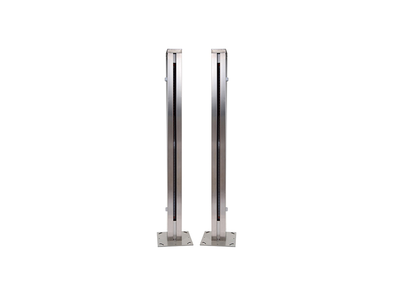
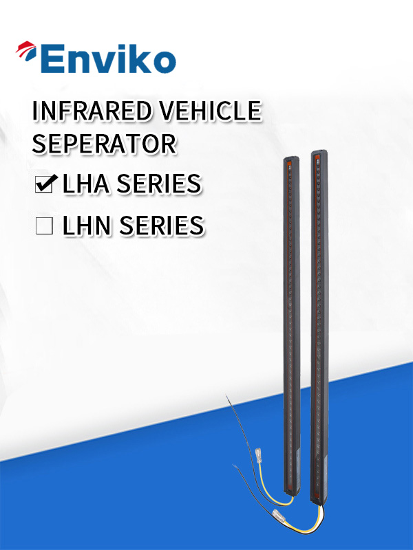
רכב אינפרא אדום
תיאור קצר:
פונקציית חימום חכמה.
תפקוד אבחון עצמי.
פלט זיהוי פונקציית פלט אזעקה.
תקשורת מסדרת RS 485.
99.9% דיוק עבור הפרדת רכב.
דירוג הגנה: IP67.
פירוט המוצר
תגיות מוצר

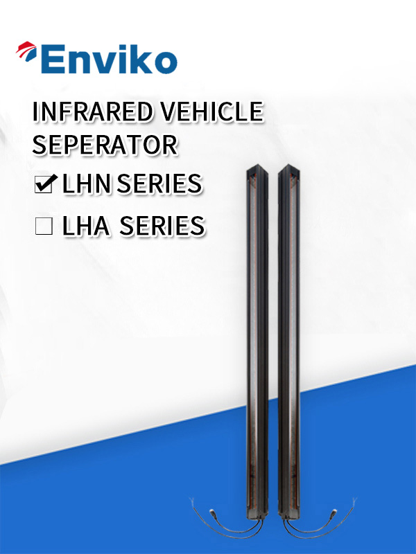
תכונות מוצר
| מאפיינים | Dמכתב |
| Rקרן קולטתכוחאיתור | 4 רמות של חוזק אלומה מוגדרות, זה נוח להתקנה ותחזוקה בשטח. |
| Dפונקציית איאגנוזה | נוריות אבחון מספקות אמצעי פשוט לניטור ביצועי החיישן. |
| פלטים | שתי יציאות בדידות(Dפלט זיהוי ופלט אזעקה, NPN/PNP אופציונלי),ועודEIA-485 תקשורת טורית. |
| פונקציית מיגון | Cמזהה אוטומטית את הכשלים של הפולט או המקלט ומצב הזיהום של העדשה, זה עדיין יכול לעבוד במצב של כשלים, בינתיים לשלוח הוראות אזהרה ופלטי אזעקה. |
1.1 רכיבי המוצר
המוצרים כוללים את הרכיבים הבאים:
● פולט ומקלט;
● כבל אחד בן 5 ליבות (פולט) ואחד בן 7 ליבות (מקלט) ניתוק מהיר אחד;
● כיסוי מוגן;
1.3 עקרון עבודת המוצר
המוצר מורכב בעיקר ממקלט ופולט, תוך שימוש בעקרון של ירי נגד.
למקלט ולפולט יש אותה כמות של LED ותא פוטואלקטרי, ה-LED בפולט ובתא הפוטואלקטרי במקלט נגיעה סינכרונית, כאשר האור כבוי, המערכת עושה את הפלט.
מפרט מוצר
| Cתוכן | מפרטים |
| Oמספר הציר הפטי (קרן);מרווח ציר אופטי;אורך הסריקה | 52;24 מ"מ;1248 מ"מ |
| Eאורך גילוי אפקטיבי | 4 ~ 18 מ' |
| רגישות מינימלית לאובייקט | 40 מ"מ(סריקה ישרה) |
| מתח אספקה | 24V DC±20%; |
| לְסַפֵּקנוֹכְחִי | ≤200mA; |
| Dפלטים iscrete | Transistor PNP/NPN זמין,יציאות זיהוי ויציאות אזעקה,150mA מקסימום.(30V DC) |
| יציאות EIA-485 | EIAתקשורת טורית -485 מאפשרת למחשב לעבד נתונים סריקה ומצב מערכת. |
| Iיציאות אור חיווי | Wנורית מצב אורקינג (אדום), נורית הפעלה (אדום), נורית עוצמת קרן קליטה (אדום וצהוב כל אחד) |
| Rזמן תגובה | ≤10 אלפיות השנייה(יָשָׁרלִסְרוֹק) |
| ממדים(אורך רוחב גובה) | 1361 מ"מ× 48 מ"מ× 46 מ"מ |
| הפעלהמַצָב | טֶמפֶּרָטוּרָה:-45℃~ 80℃,לחות יחסית מקסימלית:95% |
| Cבנייה | aאלומיניוםדיור עם גימור אנודייז שחור;חלונות זכוכית משוריינת |
| דירוג סביבתי | IEC IP67 |
הוראות נורית חיווי
נורות LED משמשות לציון מצב העבודה ומצב הכשל של המוצרים, לפולט ולמקלט יש אותה כמות של נורית חיווי.נורות ה-LED ממוקמות בחלק העליון של הפולט והמקלט, המוצג באיור 3.1
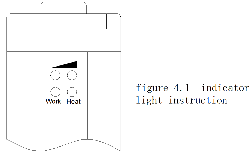
Diagram 3.1הוראת נורית חיווי (מצב עבודה;כּוֹחַאוֹר)
| נורית חיווי | פולט | מַקְלֵט |
| עֲבוֹדָה(אָדוֹם): נורית מצב עבודה | on:אוֹרמָסָךעובד בצורה לא נורמלית*כבוי:אוֹרצוללn עובד כרגיל | on:אוֹרמָסָךחסום**כבוי:אוֹרמָסָךאינו חסום |
| חום (אדום):Pאור תחתית | on:קרן קולטת היאחזק (הרווח המופרז הוא יותר מ8)הַברָקָה:קרן קולטת היא לְהִתְעַלֵף(הרווח המופרז הואפָּחוֹתיותר מ-8) | |
הערה: * כאשר מסך האור פועל בצורה לא תקינה, פלטי אזעקה נשלחים;** כאשר מספר הציר האופטי שהםחָסוּםגדול ממספר קבוצת הקורות, פלטי זיהוי שולחים.
תרשים3.2 הוראת נורית חיווי(קבלת חוזק אלומה/אוֹר)
| נורית חיווי | פולט ומקלט | מֵעִיר |
| (①אדום, ②צהוב) | ①כבוי,②כבוי:רווח מופרז:16 | 1 באורך של 5 מ', הרווח המופרז הוא יותר מ-16;באורך הזיהוי המרבי, הרווח המופרז הוא 3.2 כאשר הרווח המופרז קטן מ8, הpנורית התחתית מהבהבת. |
| ①על,②כבוי:רווח מופרז: 12 | ||
| ①כבוי,②על:רווח מופרז:8 | ||
| ①על,②על:רווח מופרז:4 |
מידות מוצר וחיבור
מידות המוצר 4.1 מוצגות באיור 4.1;
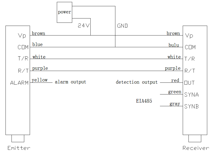
חיבור מוצר 4.2 מוצג באיור 4.2

הוראות איתור
5.1 חיבור
ראשית, הגדר את המקלט ואת הפולט של מסך האור לפי איור 4.2, וודא שהחיבור נכון (כיבוי בעת החיבור), לאחר מכן, הגדר את הפולט והמקלט פנים אל פנים במרחק האפקטיבי.
5.2 יישור
הפעל את המתח (24v DC), לאחר שני מהבהבים של נורית חיווי מסך האור, אם נורית ההפעלה (אדום) של הפולט והמקלט דולקת, בזמן שנורית מצב העבודה (אדום) כבויה, מסך האור הוא מיושר.
אם נורית מצב העבודה (אדומה) של הפולט דולקת, ייתכן שהפולט ו(או) המקלט תקלו, ויש צורך לתקן אותם בחזרה למפעל.
אם נורית מצב העבודה (אדום) של המקלט דולקת, ייתכן שמסך האור לא יהיה מיושר, הזיז או סובב את המקלט או הפולט באיטיות וצפה, עד שנורית מצב העבודה של המקלט כבה (אם לא ניתן ליישר אותו לאחר זמן רב, זה אומר להיות תיקון חזרה למפעל).
אזהרה: אסור להכניס חפצים במהלך תהליך היישור.
אור חוזק האלומה המקבל (אדום וצהוב כל אחד) של הפולט והמקלט קשור למרחק העבודה האמיתי, הלקוחות צריכים לווסת על סמך השימוש בפועל.פרטים נוספים בתרשים 3.2.
5.3 זיהוי מסך אור
יש להפעיל את הזיהוי בתוך המרחק האפקטיבי וגובה הזיהוי של מסך האור.
באמצעות העצמים שגודלם 200*40 מ"מ לזיהוי מסך האור, ניתן היה להפעיל את הזיהוי בכל מקום בין הפולט למקלט, בדרך כלל בקצה המקלט, שקל יותר לצפייה.
במהלך הזיהוי, זהה שלוש פעמים במהירות קבועה (>2 ס"מ/שנייה) סביב האובייקט.(הצד הארוך מאונך לקורה, מרכז אופקי, מלמעלה למטה או מלמטה למעלה)
במהלך התהליך, נורית מצב העבודה (אדום) של המקלט צריכה להיות דולקת כל הזמן, ההצהרה התואמת לפלטי הזיהוי לא צריכה להשתנות.
מסך האור פועל כרגיל כאשר הוא עומד בדרישות לעיל.
התאמה
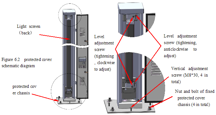
אם מסך האור אינו במצב העבודה הטוב ביותר (ראה איור 6.1 ו-דאיאגרמה6.1), יש להתאים אותו.Sאיור איור 6.2.
1,Tהכיוון האופקי: כוונן את המוגןכיסוי: 4 שחררו את האוםof תוקןpנסובבמארז כיסוי, סיבוב ידני של הכיסוי המוגן;
התאם אתאוֹרמסך: שחרר את בורג כוונון הרמה הימני, והדק את השמאלירָמָהלְהַתְאִיםmentבורג עם כיוון השעון כדי להתאים אתאוֹרמָסָך.להיפך, להתאים הפיךאוֹרמָסָך.Pשימו לב להתאים את כמות הבורג השמאלי והימני;
2,Tהכיוון האנכי: 4 שחרר את האוםof מארז כיסוי מוגן קבוע, 4 בורג כוונון אנכי להתאמת ההתקנה על המרכב;
3,To להתבונן באינדיקטור של המדינה, לאוֹרהמסך במצב העבודה הטוב ביותר, הדקו את אומי תיקון השלדה ואת כל הברגים הרופפים.
סט מפעל
ניתן לשנות את הפרמטרים הבאים באמצעות ממשק טורי EIA485, ערכת היצרן היא:
1 כאשר יציאות מופעלות, מכסה רציף ציר אופטי מספר N1=5;
2 כאשר ציר אופטי רציף N1-1 (מינימום 3) חסום, זמן אזעקת תקלה: T = 6(60s);
3 סוג פלט זיהוי: NPN פתוח בדרך כלל;
4 סוג פלט אזעקה: NPN פתוח בדרך כלל;
5 גישת סריקה: סריקה ישרה;
ממשק תקשורת טורית
8.1 ממשק תקשורת טורית
● ממשק טורי EIA485,תקשורת אסינכרונית חצי דופלקס;
● קצב שידור: 19200;
● פורמט תווים: סיביות התחלה אחת, 8 סיביות נתונים, סיביות עצירה אחת, ללא זוגיות, שליחה וקבלה של נתונים מההתחלה הנמוכה
8.2 שלח וקבל פורמט נתונים
● פורמט נתונים: כל הנתונים הם בפורמט הקסדצימלי, כל שליחה וקבלה של נתונים כוללים: 2 ערך בתים של פקודה, 0~בתים מרובים של נתונים, בית אחד של קוד בדיקה;
● 4 פקודות שליחה וקבלה בסך הכל, כפי שמוצג בתרשים 8.1
תרשים 8.1
ערך ההזמנה
הגדרה (הקסדצימלית) פורמט נתונים (עבור מסך אור ממשק טורי)
קבל (הקסדצימלי) שלח (הקסדצימלי)*
0x35、0x3A סט מידע מצב מסך אור 0x35,0x3A,N1, T,B,CC 0x35,0x3A,N,N1,T,B,CC
0x55、0x5A אור מידע מצב מסך משדר 0x55,0x5A,CC 0x55,0x5A,N,N1,T,B,CC
0x65、0x6A העברת מידע אלומת מסך אור (לסירוגין) 0x65,0x6A,n,CC 0x65,0x6A,n,D1,D2,…,Dn,CC
0x95、0x9A העברת מידע אלומת מסך אור (רציף) 0x95,0x9A,n,CC 0x95,0x9A,n,D1,D2,…,Dn,CC
N1 כאשר הפעיל יציאות, המספר המתמשך מרחיק את האלומה, 0 < N1 < 10 ו- N1 < N;
T הזמן שאלומת האור הרציפה של N1-1 תישמר בחוץ (10*T שנייה), פלט אזעקה כאשר לאורך זמן, 0<T <= 20;
B פלט זיהוי (ביט 0 , המקלט)、0(bit 1)、פלט אזעקה(ביט 2, הפולט)סימן פתיחה/סגירה,0 פתוח באופן קבוע,1 נסגר באופן קבוע.סימן סוג סריקה (bit 3),0 סריקה ישרה, סריקה צולבת אחת.0x30 ~ 0x3F.
N המספר הכולל של הקורה;
n מספר הקטעים שנדרשו להעברת המידע של האלומה (8 אלומות מהוות קטע אחד), 0 < n <= N/8, כאשר ל-N/8 יש שאריות, הוסף קטע אחד;
D1,…,Dn מידע של כל קטע אלומה (עבור כל אלומות, ההולכה היא 0, הכיסוי הוא 1);
CC 1 Byte check code, שהוא הסכום של כל המספר לפני (הקסדצימלי) ולבטל את ה-8 הגבוה
8.3 הוראת שליחה וקבלה של נתונים
1 הגדרות האתחול של מסך האור הן מצב קליטת תקשורת טורית , מוכן לקבלת נתונים.כל פעם מקבל נתונים אחד, על פי מצוות קבלת נתונים, הגדרת תוכן נתונים והגדר מצב תקשורת טורית לשליחה, המשך נתונים שנשלחו.לאחר שליחת הנתונים, הגדר שוב את מצב התקשורת הטורית לקבלה.
2 רק כאשר מקבלים את הנתונים הנכונים, מתחיל תהליך שליחת הנתונים.הנתונים השגויים שהתקבלו כוללים: קוד בדיקה שגוי, ערך הזמנה שגוי (לא אחד מ-0x35、0x3A / 0x55、0x5A / 0x65、0x6A / 0x95、0x9A));
3 הגדרות האתחול של המערכת של הלקוח נדרשות להיות מצב שליחה של תקשורת טורית, בכל פעם לאחר שליחת הנתונים יש להגדיר את מצב התקשורת הטורית לקבל מיד, להתכונן לקבלת הנתונים ששלח מסך אור.
4 כאשר מסך האור מקבל את הנתונים שנשלחו על ידי המערכת של הלקוח, שלח נתונים לאחר מחזור סריקה זה.לכן, עבור המערכת של הלקוח, לאחר שליחת נתונים בכל פעם, בדרך כלל, יש לשקול 20~30ms המתנה לקבלת נתונים.
5 לציווי של ערכת מידע על מצב מסך אור (0x35、0x3A), עקב הצורך בכתיבת ה-EEPROM, יהיה יותר זמן שישמש לשליחת נתונים.עבור פקודה זו, ממליץ ללקוח לשקול כ-1 שניות המתנה לקבלת נתונים.
6 במצב רגיל, מערכת הלקוח תשתמש בפקודת העברת מידע קרן אור (0x65、0x6A/ 0x95、0x9A) לעתים קרובות, אך הגדרת מידע מצב מסך אור (0x35、0x3A) ופקודת שידור (0x55、0x5A) משמשות רק כאשר נדרש.לכן, אם אין צורך, ממליץ בחום לא להשתמש במערכת הלקוח (במיוחד פקודת הגדרת מידע מצב מסך קל).
7 מכיוון שהמצב של הממשק הטורי EIA485 הוא חצי דופלקס אסינכרוני, עקרון העבודה של השליחה לסירוגין שלו (0x65、0x6A) ושליחה רציפה (0x95、0x9A) הוא במילים הבאות:
● שליחה לסירוגין: במהלך האתחול, הגדר את הממשק הטורי לקבלה, כאשר הפקודה ממערכת הלקוח מתקבלת, הגדר את הממשק הטורי לשידור.לאחר מכן שלח נתונים על סמך הפקודה שהתקבלה, לאחר שליחת הנתונים, הממשק הטורי יאופס לקבלה.
● שליחה רציפה: כאשר ערך הפקודה המתקבל הוא 0x95、0x9A, התחל לשלוח מידע רצוף על אלומת מסך האור.
● במצב של שליחה רציפה, אם מישהו מהציר האופטי במסך האור נשמר בחוץ, שלח נתונים סדרתיים בנסיבות שכל מעגל סריקה הסתיים בזמן שהממשק הטורי זמין, בינתיים, הממשק הטורי יהיה להיות מוגדר לשדר.
● במצב של שליחה רציפה, אם לא נשמר בחוץ ציר אופטי במסך האור והממשק הטורי זמין (לאחר שידור נתונים אלו), הממשק הטורי יוגדר לקלוט, ממתין לקבלת נתונים.
● אזהרה: במצב של שליחה רציפה, מערכת הלקוח היא תמיד הצד שמקבל נתונים, כאשר יש צורך בשידור, היא יכולה להמשיך רק בנסיבות שמסך האור לא נשמר וחייב להסתיים תוך 20 ~ 30 שניות לאחר נתונים מתקבלים, אחרת, זה עלול לגרום לבעיות תקשורת טורית שלא ניתן לחזות, וזה עלול לגרום נזק לממשק הטורי, כאשר הוא גרוע יותר.
הוראות של Light-Screen וכיצד לתקשר עם מחשב
9.1 סקירה כללית
Light-Screen משמש להגדרת תקשורת בין מסך האור מסדרת LHAC למחשב, אנשים יכולים להגדיר ולזהות את מצב העבודה של מסך האור באמצעות Light-Screen.
9.2 התקנה
1 דרישות התקנה
● מערכת ההפעלה Windows 2000 או XP בסינית או באנגלית;
● בעל ממשק טורי RS232 (9 פינים);
2 שלבי התקנה
● פתח את התיקיות: תוכנת תקשורת PC\מתקין;
● לחץ על קובץ ההתקנה, התקן את Light-Screen;
● אם כבר יש לו Light-Screen, ההתקנה מבצעת תחילה פעולות מחיקה, ולאחר מכן התקן מחדש את התוכנה
● במהלך ההתקנה, עליך לציין תחילה את ספריית ההתקנה ולאחר מכן ללחוץ על הבא כדי להתקין
9.3 הוראות הפעלה
1 לחץ על "התחל", מצא את "תוכנית(P)\Light-Screen\Light-Screen", הפעל את Light-Screen.
2 לאחר הפעלת Light-Screen, תחילה יופיע הממשק המוצג באיור 9.1, הממשק השמאלי;לחץ על הממשק או המתן 10 שניות, התמונה בצד ימין של איור 9.1 מופיעה.
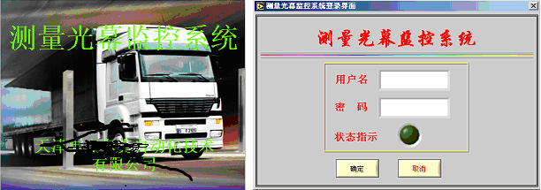
3 היכנסו לשם המשתמש: abc, סיסמאות: 1, ואז לחצו על "אישור", היכנסו לממשק העבודה של Light Screen, כפי שמוצג באיור 9.2 ובאיור 9.3.
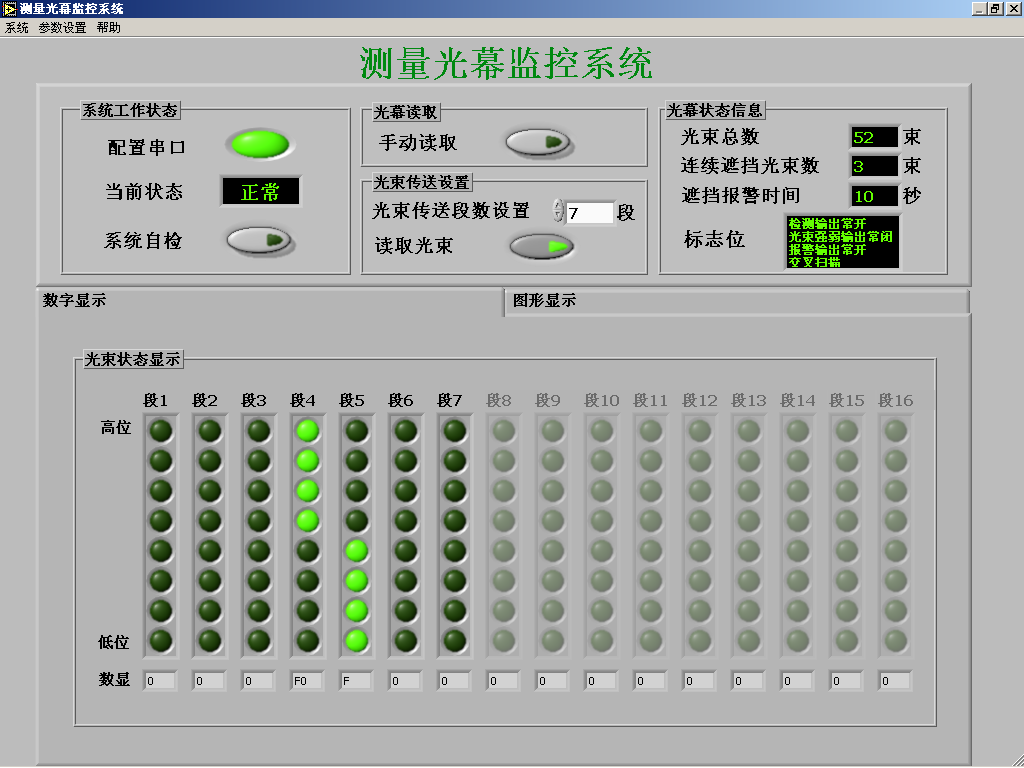
איור 9.2 ממשק עבודה של תצוגה דיגיטלית
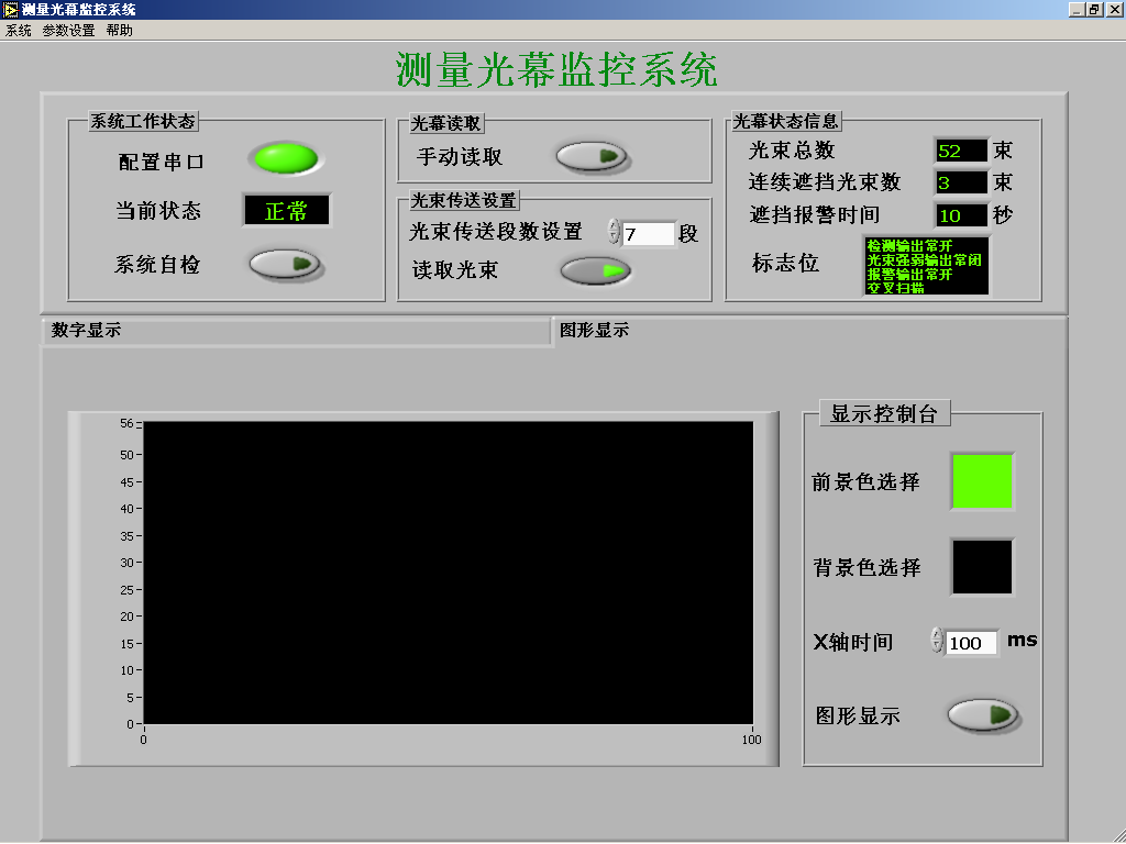
איור 9.3 ממשק עבודה של תצוגה גרפית
4 ממשק העבודה של התצוגה משמש להצגת מידע העבודה ומידע המצב של מסך האור, פרטים נוספים במילים הבאות:
● מצב עבודה של המערכת: תיבת המצב הנוכחית מציינת אם התקשורת הטורית תקינה או לא, לחץ על לחצן הבדיקה העצמית של המערכת, המשך בבדיקה טורית;
● קריאת מסך אור: לחץ על לחצן קריאה ידנית, קרא את פרטי מצב מסך האור פעם אחת;
● הגדרות שידור אלומה: ערכת מקטעי שידור אלומה מגדירה את מספר המקטע של אלומת המשדר, כאשר כפתור אלומת הקריאה פועל, שליחה מתמשכת מידע אלומה;
● מידע על מצב מסך האור: הצג את מספר האלומה הכוללת של מסך האור, מספר האלומה הרציפה שנחסמה, זמן אזעקת החסימה, (זמן אזעקת התקלה של פחות מקרן N1-1 רציפה שנחסמה), סימנים כגון זיהוי יציאות, יציאות חוזק אלומה (לא בשימוש), יציאות אזעקת תקלות נפתחות/סגורות באופן קבוע סימן וסוג סריקה (סריקה ישרה/סריקה צולבת), וכו'
● תצוגה דיגיטלית (איור 9.2): נורית חיווי (סדר לפי קטע, הציר האופטי התחתון הוא הראשון) מציין את ההצהרה של כל אלומה, האור דולק כשהיא חסומה, האור כבוי כשהיא לא חסומה.
● תצוגה גרפית (איור 9.3): הצג את צורת האובייקטים שעוברים דרך מסך האור בפרק זמן מסוים.
● קונסולת תצוגה גרפית: בחר את צבע הגרפיקה (בחירת החזית- צבע הרקע של הגרפיקה (בחירת הרקע-), רוחב הזמן של חלון התצוגה (זמן של ציר X-X), וכו' כאשר הגרפיקה תצוגה ( כפתור פועל, התחל באיסוף נתונים והצג.
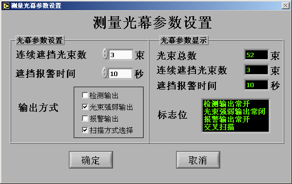
5 בעת ביצוע הגדרות פרמטרים לבחירה/תפריט פרמטרים של המערכת, הצג את ממשק הגדרת הפרמטרים (איור 9.4), על מנת להגדיר את פרמטרי העבודה של מסך האור, פרטים נוספים הם במילים הבאות:
● הגדרת פרמטרים של מסך אור: הגדרת מספר האלומה שתישאר בחוץ, זמן אזעקה לחסום, מצב הפלט של כל סימנים וכו'. ביניהם: סימנים כגון פלטי זיהוי פלטי חוזק אלומה (לא בשימוש), פלטי אזעקת תקלות מופיעים באופן קבוע סגור כאשר נבחר (יש√ בתוך התיבה), סוג הסריקה הוא סריקה צולבת כאשר נבחר.;
● תצוגת פרמטרים של מסך אור: הצג את הסימנים של מסך האור, כגון המספר הכולל של האלומה, מספר האלומה שנחסמה ברציפות, זמן אזעקת הבלוק, פלטי זיהוי, פלטי חוזק אלומה (לא בשימוש), פלטי אזעקת תקלות באופן קבוע שלט פתיחה/סגירה וסוג סריקה (סריקה צולבת/סריקה ישרה) וכו'.
● לאחר הגדרת פרמטרי מסך האור, לחץ על כפתור אישור, הצג תיבת איפוס פרמטרי מסך אור, לחץ על כפתור האישור של התיבה, כדי להגדיר את פרמטרי מסך האור, לחץ על כפתור ביטול, אם אינך רוצה להגדיר את פרמטרים.
● לחץ על לחצן הביטול בממשק הגדרת הפרמטרים כדי לצאת מממשק זה.
התקשורת בין מסך האור למחשב
10.1 החיבור בין מסך האור למחשב
השתמש בממיר EIA485RS232 לחיבור, חבר את שקע 9 הליבות של הממיר עם הממשק הטורי 9 פינים של המחשב, הקצה השני של הממיר מתחבר לקו הממשק הטורי EIA485 (2 קווים) של מסך האור (מוצג באיור 4.2 ).חבר את ה-TX+ עם SYNA (קו ירוק) של המקלט של מסך האור, חבר את TX- עם ה-SYNB (קו אפור) של המקלט של מסך האור.
10.2 התקשורת בין מסך האור למחשב
1 חיבור: חבר את הפולט והמקלט כפי שמוצג באיור 5.2, וודא שהחיבור תקין (כיבוי בזמן חיבור הכבלים), הגדר את הפולט והמקלט פנים אל פנים ובצע יישור.
2 הדלק את מסך האור: הפעל את ספק הכוח (24V DC), ממתין למסך האור למצב עבודה רגיל (פרטים נוספים בסעיף 6, הוראת זיהוי)
3 תקשורת עם PC: הפעל את התוכנית Light-Screen, בהתאם לסעיף 9, הוראות של Light Screen וכיצד לתקשר עם PC.
10.3 זיהוי מצב והגדרת פרמטרים של מסך האור
1 זיהוי מצב העבודה של מסך האור באמצעות ממשק תצוגה דיגיטלית: באמצעות האובייקט שגודלו הוא 200*40 מ"מ הנע על כל ציר אופטי, נורית החיווי בממשק התצוגה הדיגיטלית דולקת או כבויה בהתאם (קרן הקריאה(读取光束) יש להאיר את הכפתור במהלך הפעולה)
2 בעת שימוש בממשק הגדרת פרמטרים לקביעת הפרמטרים של מסך האור, עליך לשים לב לסעיף 9, הוראות של Light Screen וכיצד לתקשר עם מחשב

